SLDS151A May 2009 – June 2015 TMP814
PRODUCTION DATA.
- 1 Features
- 2 Applications
- 3 Description
- 4 Revision History
- 5 Pin Configuration and Functions
- 6 Specifications
- 7 Detailed Description
- 8 Application and Implementation
- 9 Power Supply Recommendations
- 10Layout
- 11Device and Documentation Support
- 12Mechanical, Packaging, and Orderable Information
Package Options
Mechanical Data (Package|Pins)
- PW|20
Thermal pad, mechanical data (Package|Pins)
- PW|20
Orderable Information
1 Features
- Predriver for Single-Phase Full-Wave Drive
- PNP-NMOS is Used as an External Power TR, Enabling High-Efficiency Low-Consumption Drive by Means of the Low-Saturation Output and Single-Phase Full-Wave Drive (PMOS-NMOS Also Applicable)
- External PWM Input Enabling Variable Speed Control
- Separately-Excited Upper Direct PWM (f = 25 kHz) Control Method, Enabling Highly Silent Speed Control
- Compatible with 12-V, 24-V, and 48-V Power Supplies
- Current Limiter Circuit Incorporated
- Chopper Type Current Limit at Start
- Reactive Current Cut Circuit Incorporated
- Reactive Current Before Phase Change is Cut to Enable Silent and Low-Consumption Drive
- Minimum Speed Setting Pin
- Minimum Speed Can Be Set With External Resistor. Start Assistance Circuit Enables Start at Extremely Low Speed.
- Constant-Voltage Output Pin for Hall Bias
- Lock Protection and Automatic Reset Functions Incorporated
- FG (Rotation Speed Detection) and RD (Lock Detection) Output
2 Applications
- Server Fans (Up to 48 V)
- Appliance Fans (Up to 48 V)
3 Description
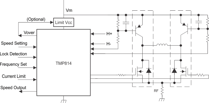
The TMP814 is a single-phase bipolar variable speed fan motor predriver that works with an external PWM signal. A highly efficient, quiet and low-power consumption motor driver circuit, with a large variable speed, can be implemented by adding a small number of external components.
This device is optimal for driving large scale fan motors (with large air volume and large current) such as those used in servers and consumer products.
Device Information(1)
| PART NUMBER | PACKAGE | BODY SIZE (NOM) |
|---|---|---|
| TMP814 | TSSOP (PW) | 4.40 mm x 6.50 mm |
- For all available packages, see the orderable addendum at the end of the data sheet.
Simplified Schematic
