SLUS544G September 2003 – April 2017 UCC28220 , UCC28221
PRODUCTION DATA.
- 1 Features
- 2 Applications
- 3 Description
- 4 Revision History
- 5 Device Comparison Table
- 6 Pin Configuration and Functions
- 7 Specifications
- 8 Detailed Description
- 9 Application and Implementation
- 10Power Supply Recommendations
- 11Layout
- 12Device and Documentation Support
- 13Mechanical, Packaging, and Orderable Information
Package Options
Refer to the PDF data sheet for device specific package drawings
Mechanical Data (Package|Pins)
- PW|16
- D|16
Thermal pad, mechanical data (Package|Pins)
Orderable Information
1 Features
- 2-MHz High-Frequency Oscillator With 1-MHz Operation Per Channel
- Matched Internal Slope Compensation Circuits
- Programmable Maximum Duty Cycle Clamp 60% to 90% Per Channel
- Peak Current Mode Control With Cycle-by-Cycle Current Limit
- Current Sense Discharge Transistor for Improved Noise Immunity
- Accurate Line Undervoltage and Overvoltage Sense With Programmable Hysteresis
- Opto-Coupler Interface
- 110-V Internal Start-Up JFET (UCC28221)
- Operates From 12-V Supply (UCC28220)
- Programmable Soft Start
2 Applications
- High Output Current (50-A to 100-A) Converters
- Maximum Power Density Designs
- High-Efficiency 48-V Input With Low Output Ripple Converters
- High-Power Offline, Telecom, and Datacom Power Supplies
3 Description
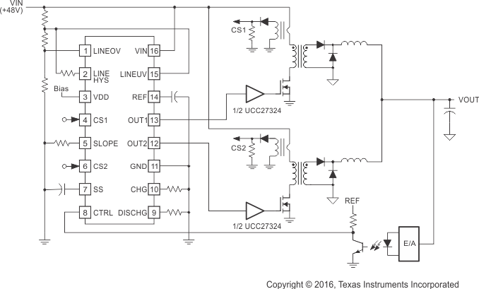
The UCC28220 and UCC28221 are a family of BiCMOS interleaved dual channel PWM controllers. Peak current mode control is used to ensure current sharing between the two channels. A precise maximum duty cycle clamp can be set to any value between 60% and 90% duty cycle per channel.
The UCC28220 has an UVLO turnon threshold of
10 V for use in 12-V supplies while UCC28221 has a turnon threshold of 13 V for systems needing wider UVLO hysteresis. Both have 8-V turnoff thresholds.
Additional features include a programmable internal slope compensation with a special circuit which is used to ensure exactly the same slope is added to each channel and a high-voltage 110-V internal JFET for easier start-up for the wider hysteresis UCC28221 version.
The UCC28220 is available in both 16-pin SOIC and low-profile TSSOP packages. The UCC28221 also comes in 16-pin SOIC package and a slightly larger 20-pin TSSOP package to allow for high-voltage pin spacing to meet UL1950 creepage clearance safety requirements.
Device Information(1)
| PART NUMBER | PACKAGE | BODY SIZE (NOM) |
|---|---|---|
| UCC28220, UCC28221 | SOIC (16) | 9.00 mm × 3.90 mm |
| TSSOP (16) | 5.00 mm × 4.40 mm | |
| UCC28221 | TSSOP (20) | 6.50 mm × 4.40 mm |
- For all available packages, see the orderable addendum at the end of the data sheet.
Typical Application
